First Version of Lithium Titanate / Ionen high power charger
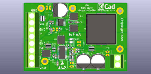

BMS for Lithium Titanat Oxide Batteries (LTO)
Why balancing a battery?
During charge and discharge cycles the different internal impedances of the cells generates a different amount of charge energy that can be stored into a single cell.
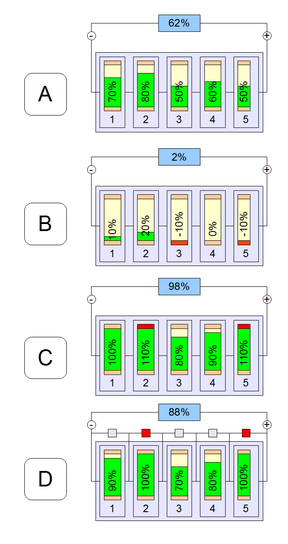
The graphic shows five cells in series.
A) During charging of the 5 cells, each single cell does not store the same amount of energy. The State of Charge (SOC) is different of all cells due to the different impedances.
B) At nearly discharged of the battery pack, cell 4 has a SOC of 0%, cell 3 and 5 is fully discharged (-10%) and cell 2 has 20%. This shows the asymmetry of the SOC. The all over SOC shows 2% which is not the correct state. The result is a possible damage of cell 3 and 5 due to deep discharge.
C) The same problem is during charging. Cell 2/5 is overcharged and can be damaged. The total SOC of the pack is only 98%.
D) When an Over Voltage Protection (OVP) is implemented inside the battery pack. The pack can only load with a SOC of 88% due to the fact that cell 2/5 are 100% and the OVP of this cells stops the charging of the battery pack. As a result the pack is not fully charged.
To prevent this asymmetry of the SOC of the single cells a BMS is necessary for all Lithium batteries.

- SYS-BMS-REQ-0001-01
- the BMS shall be able to handle LTO-Cells (special 2.4V)
- SYS-BMS-REQ-0002-01
- the balacing shall be from type "active"
- SYS-BMS-REQ-0003-01
- the minimum balace current shall be 1A
- ....
LTC3300-1 Active Balancer
Linear Description:
- Bidirectional Synchronous Flyback Balancing of Up to 6 Li-Ion or LiFePO4 Cells in Series
- Up to 10A Balancing Current (Set by Externals)
- Integrates Seamlessly with the LTC680x Family of Multicell Battery Stack Monitors
- Bidirectional Architecture Minimizes Balancing Time and Power Dissipation
- Up to 92% Charge Transfer Efficiency
- Stackable Architecture Enables >1000V Systems
- Uses Simple 2-Winding Transformers
- 1MHz Daisy-Chainable Serial Interface with 4-Bit CRC Packet Error Checking
- High Noise Margin Serial Communication
- Numerous Fault Protection Features
- 48-Lead Exposed Pad QFN and LQFP Packages
LTC6804-2 Multicell Battery Monitors
Linear Description:
- Measures Up to 12 Battery Cells in Series
- Stackable Architecture Supports 100s of Cells
-
Built-In isoSPI™ Interface:
1Mbps Isolated Serial Communications
Uses a Single Twisted Pair, Up to 100 Meters
Low EMI Susceptibility and Emissions - 1.2mV Maximum Total Measurement Error
- 290μs to Measure All Cells in a System
- Synchronized Voltage and Current Measurement
- 16-Bit Delta-Sigma ADC with Frequency Programmable 3rd Order Noise Filter
- Engineered for ISO26262 Compliant Systems
- Passive Cell Balancing with Programmable Timer
- 5 General Purpose Digital I/O or Analog Inputs:
Temperature or other Sensor Inputs
Configurable as an I2C or SPI Master - 4μA Sleep Mode Supply Current
- 48-Lead SSOP Package
BQ25708 Multi-Chemistry Battery Buck-Boost Charge Controller
TI Description:
Features
Charge 1- to 4-Cell Battery From Wide Range of Input Sources
3.5-V to 24-V Input Operating Voltage
Supports USB2.0, USB 3.0, USB 3.1 (Type C), and USB_PD Input Current Settings
Seamless Transition Between Buck and Boost Operation
Input current and Voltage Regulation (IDPM and VDPM) Against Source Overload
Power/Current Monitor for CPU Throttling
Comprehensive PROCHOT Profile, IMVP8 Compliant
Input and Battery Current Monitor
System Power Monitor, IMVP8 Compliant
Narrow-VDC (NVDC) Power Path Management
Instant-On With No Battery or Deeply Discharged Battery
Battery Supplements System When Adapter is Fully-Loaded
Ideal Diode Operation in Supplement Mode
800-kHz or 1.2-MHz Programmable Switching Frequency for 1-µH to 3.3-µH Inductor
Host Control Interface for Flexible System Configuration
SMBus Port for Optimal System Performance and Status Reporting
Hardware Pin to Set Input Current Limit Without EC Control
Integrated ADC to Monitor Voltage, Current and Power
High Accuracy Regulation and Monitor
±0.5% Charge Voltage Regulation
±2% Input/Charge Current Regulation
±2% Input/Charge Current Monitor
±5% Power Monitor
Safety
Thermal Shutdown
Input, System, Battery Overvoltage Protection
MOSFET Inductor Overcurrent Protection
Low Battery Quiescent Current
Input Current Optimizer (ICO) to Extract Max Input Power
Charge any Battery Chemistry: Li+, LiFePO4, NiCd, NiMH, Lead Acid
Package: 32-Pin 4 × 4 WQFN