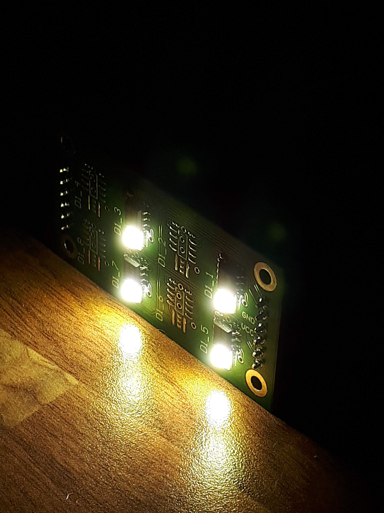
LED driver function test
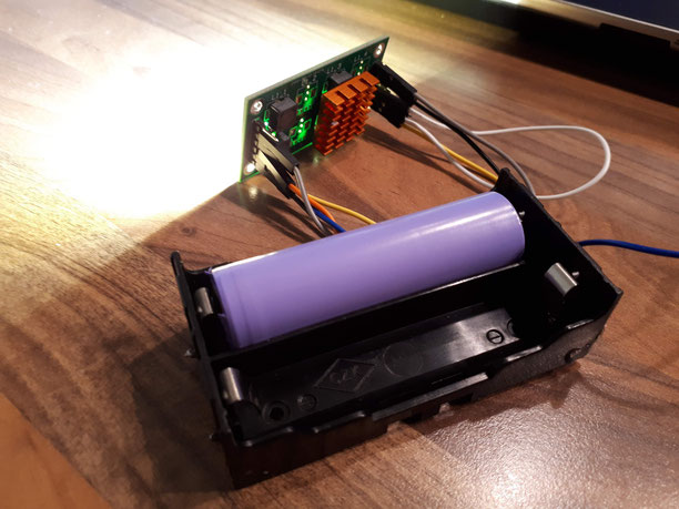
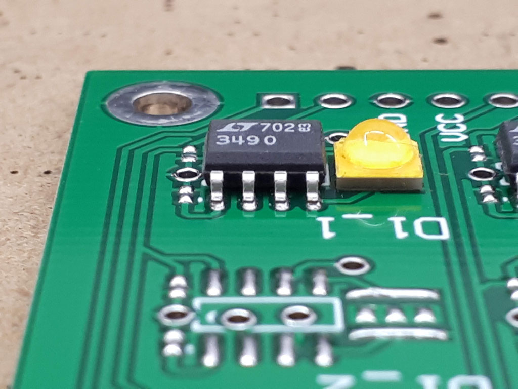
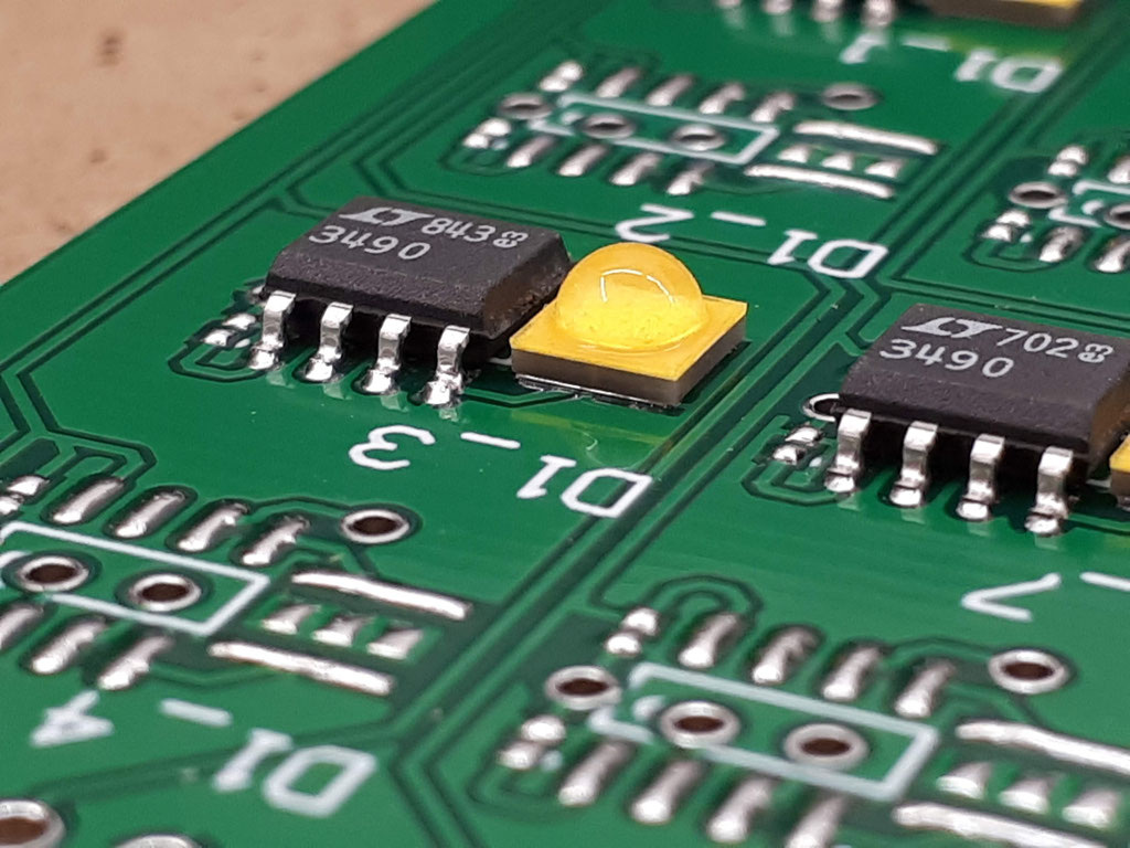
LTC3490 functional test
The LTC3490 works fine down to 1,4V input voltage. For the test I used a single cell LTO accu with ca.2200mAh capacity and a voltage range from 1.8V to 2.8V.
It is also possible to drive the LTC3490 LED driver board with a single Lithium Ionen or Lithium Polymer accu. The board runs for over 45 mins with this LTO accu.
Detailed measurements shows an power consumption of 4.5W for four LEDs. This shows an efficiency of nearly 90%.
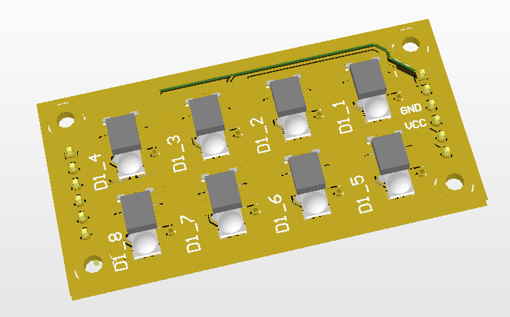
Additionaly the board can be assembled with eight LEDs so the power will increase to 9W and the lumen rises up to 1400lm.
Four groups of the eight LEDs can be indepented enabled/disabled, so a individual dimming can be done with a PWM connected to each of the four channels.
The LTC3490 board can be easly driven by an Arduino or Raspi board due to the 3.3V input compliance, but be attention to the high input current, additionaly the boards can be connection into one chain to increase the lumens.


LED driver assembly
For the assembly/soldering i ordered a laser stencil to add the solder past to the PCBs.
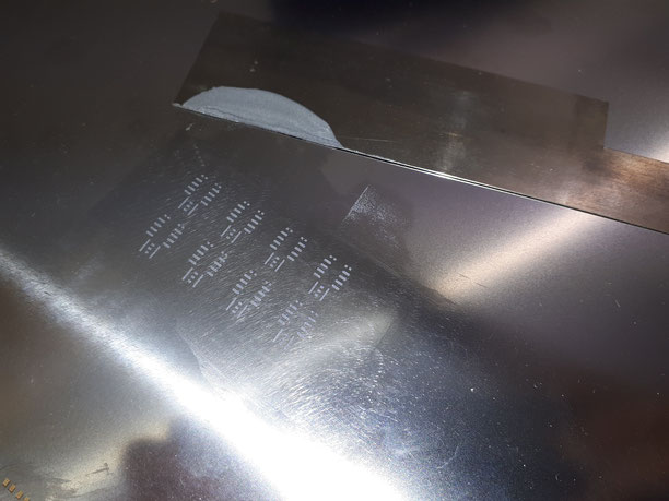
Solder added to PCB

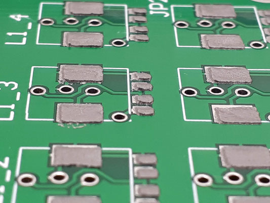

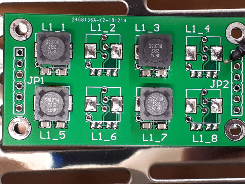
Components added
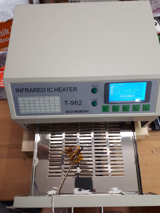
Reflow soldering


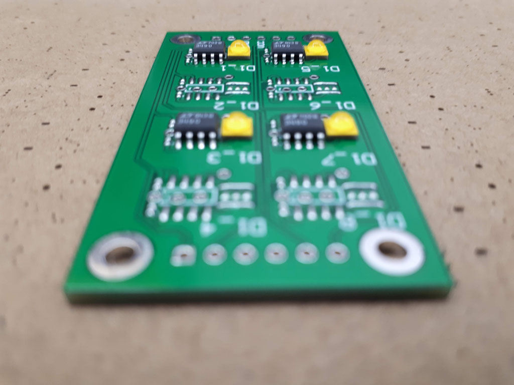
For the soldering i used the T-962 ECO-WORTHY reflow oven. (inclunding all needed patches!)

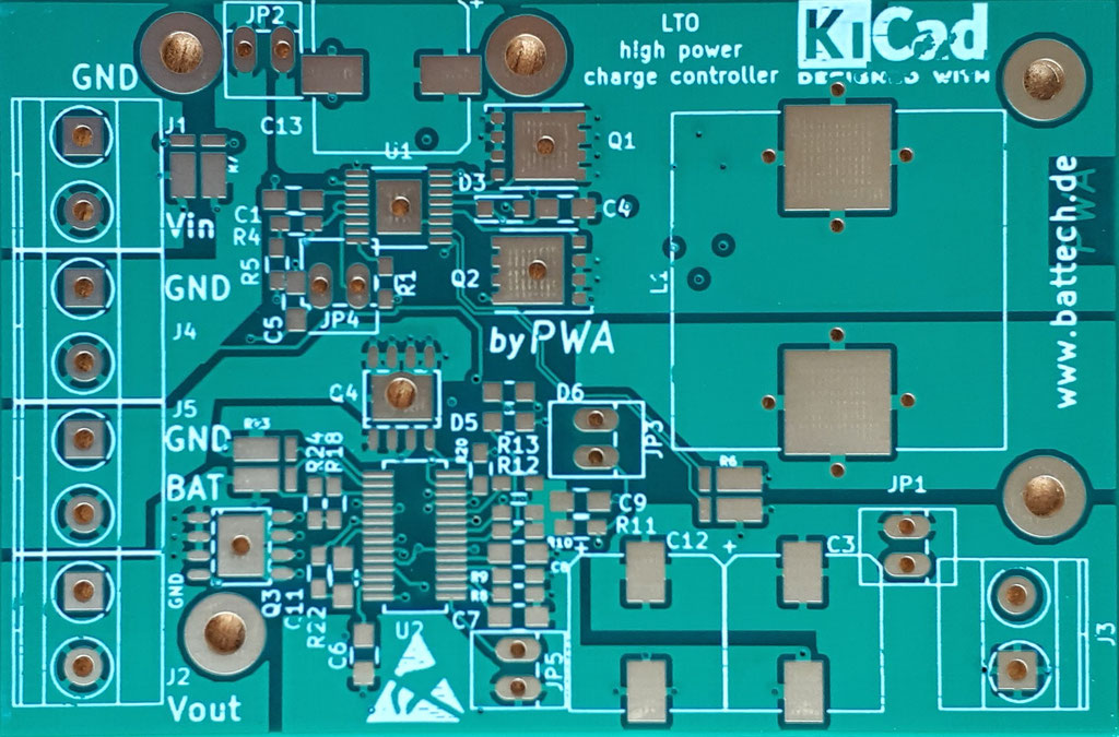
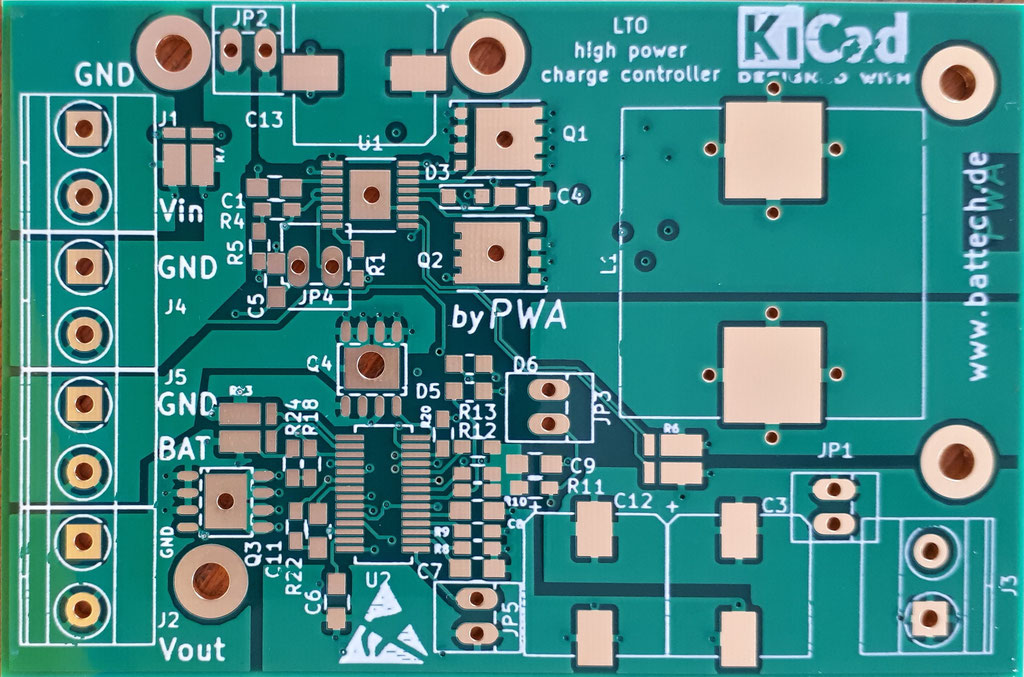
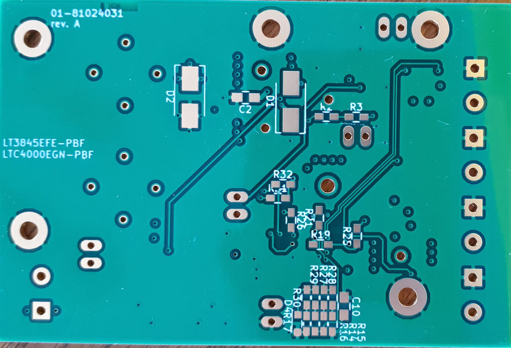
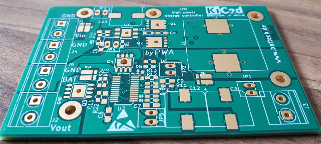
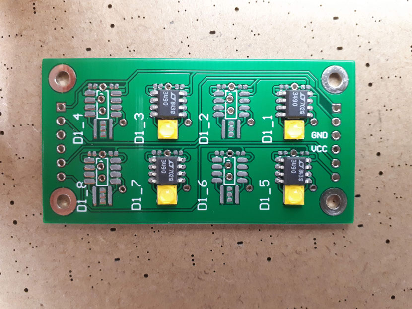
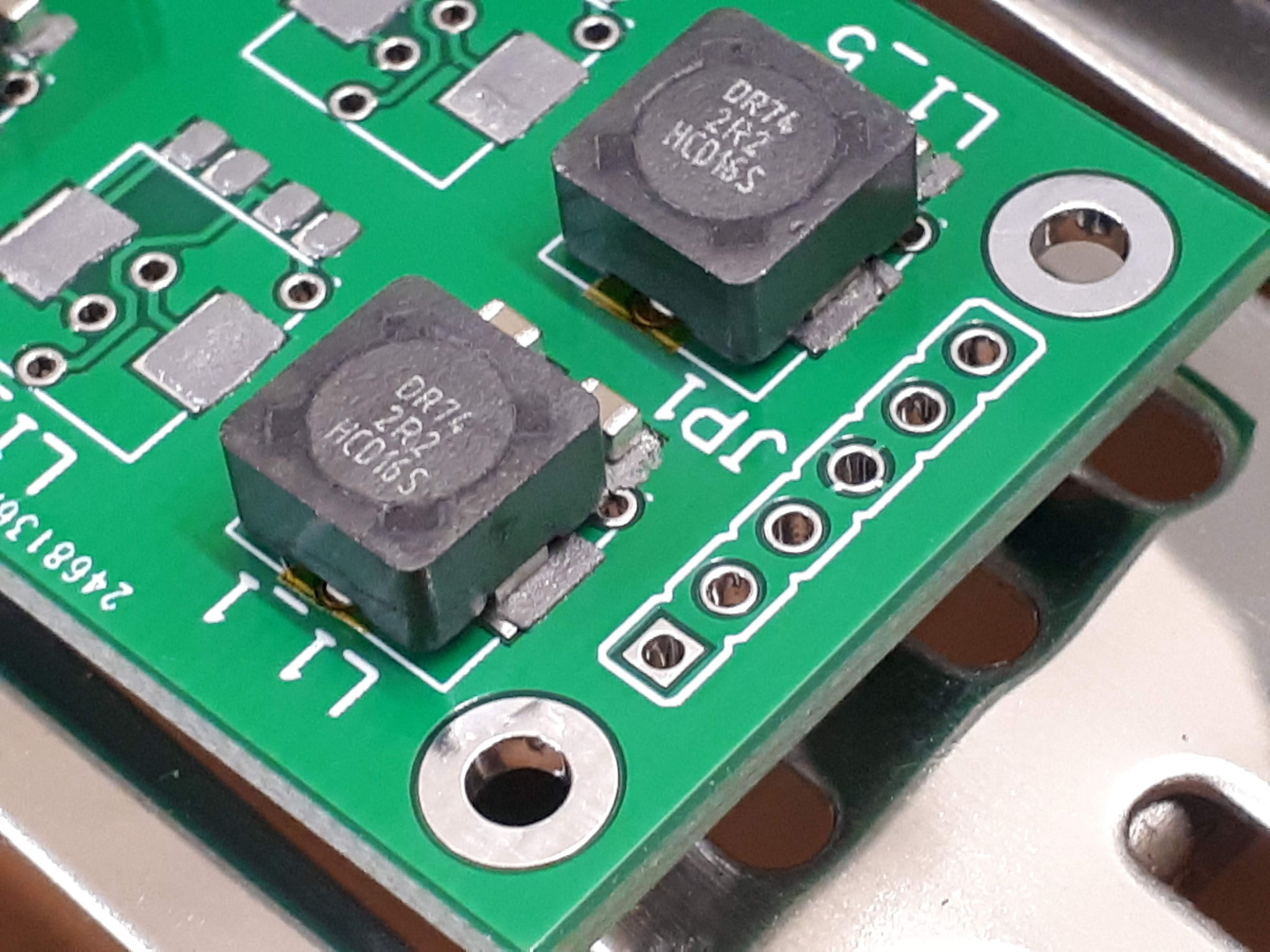
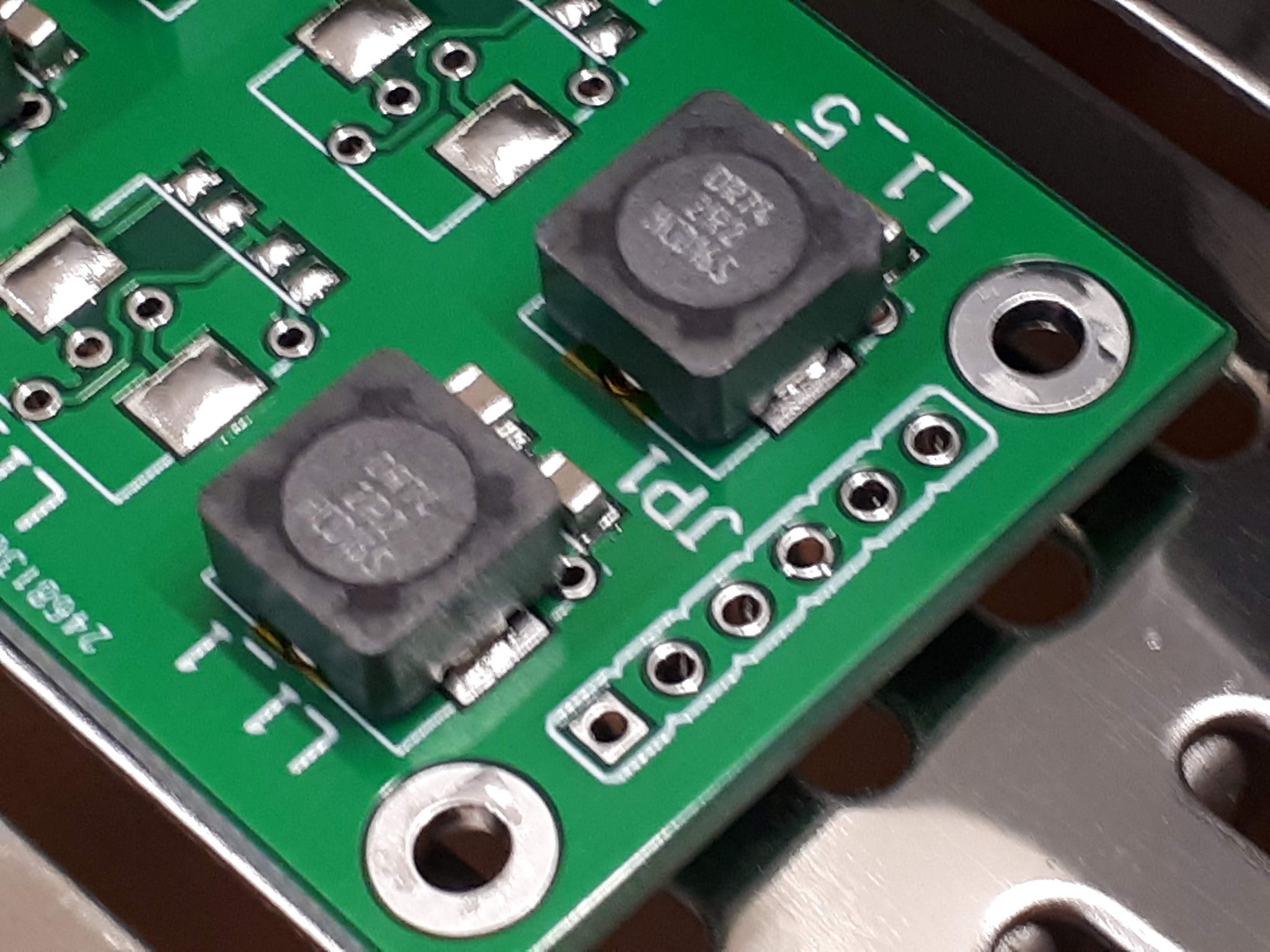
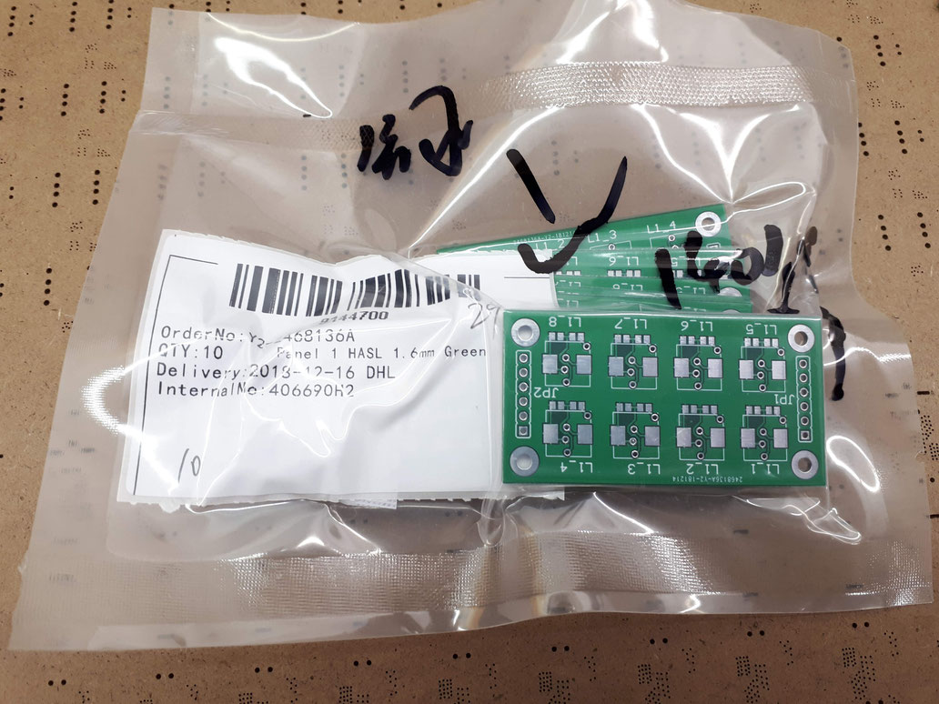
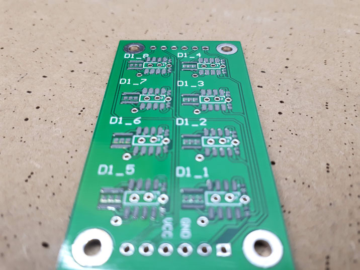
LED driver PCB's received
Prototype PCB's of the LTC3490 LED driver board received!
They are build by jlcpcb.com (Chinese prototype manufacturer) within one week. (between ordering and receiving by DHL Express)
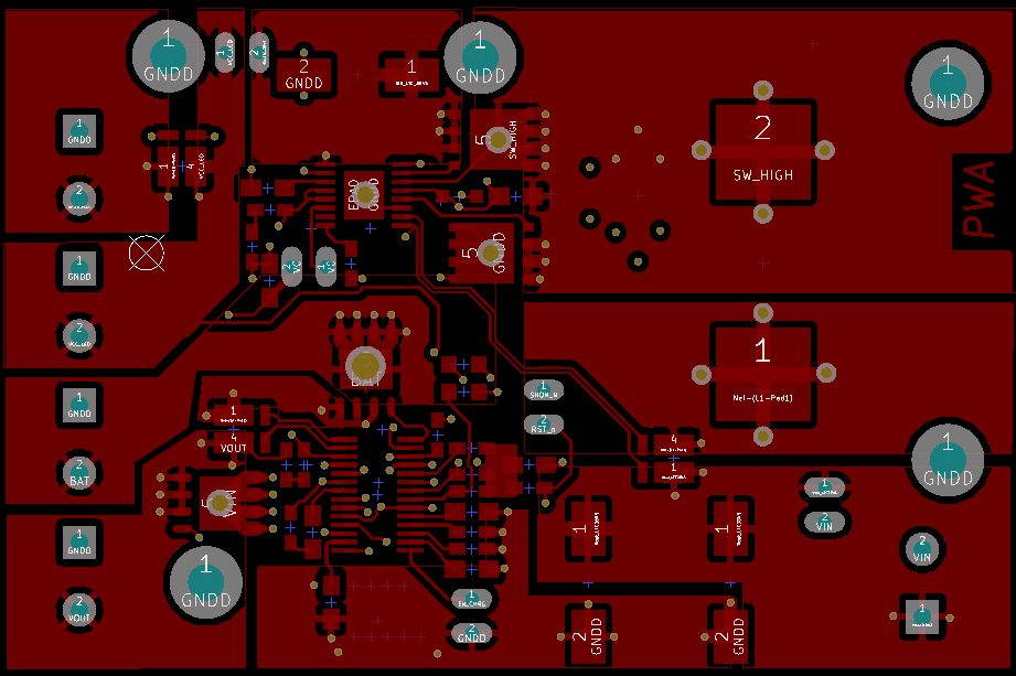
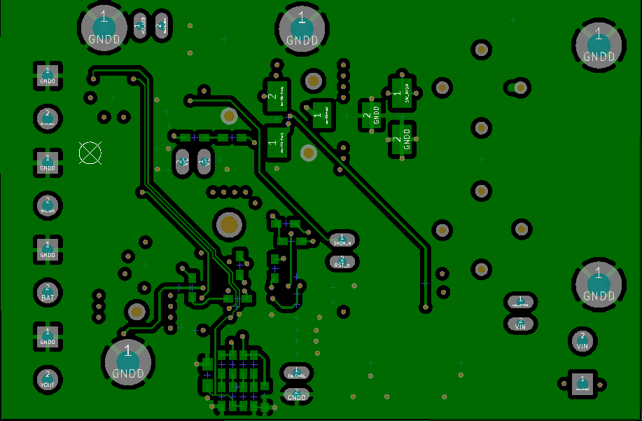
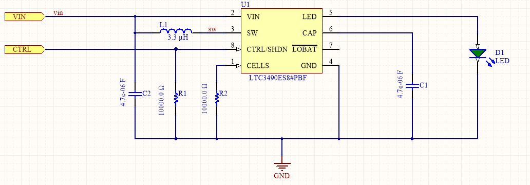
LED driver design
The schematic design and PCB design is done with Circuitmaker from Altium:
https://circuitmaker.com/Projects/Details/Meyer-Sebastian/LEDDRIVER
Project LED driver Board started
The LED driver boad can be supplied from 1V to 4V so its perfectly suitable for one cell lithium ionen battery use. I designed 8 high power LED's (3535 size, Cree or equivalent) with an constant current of 350mA.
On my first prototype i equipped four Cree LED XLAMP XPG3 4000K (RS-Online number: 1223595) with 179lm (at 25°C) -> 716lm.
The board should be driven by an 2.3V Lithium Titanate Cell (LTO).
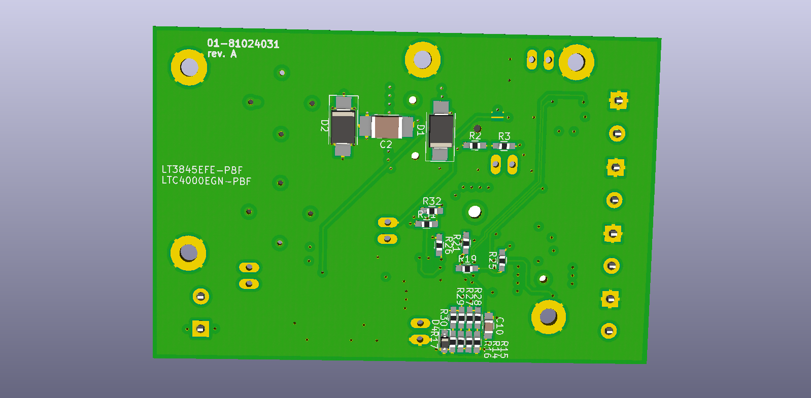
As an step up driver i decided to use the LTC3490.
Key characteristics of the LTC3490:
- 350mA Constant Current Output
- 2.8V to 4V Output Compliance
- 1- or 2-Cell NiMH or Alkaline Input or LTO battery
- Synchronous Rectification: Up to 90% Efficiency
- Fixed Frequency Operation: 1.3MHz
- Low Quiescent Current: <1mA
- Very Low Shutdown Current: <50μA
- Open LED Output Limited to 4.7V
- VIN Range: 1V to 3.2V
- Dimming Control
- Undervoltage Lockout to Protect Batteries
The efficiency is in my application around 85%-90%!
LTO BMS principle function block diagram


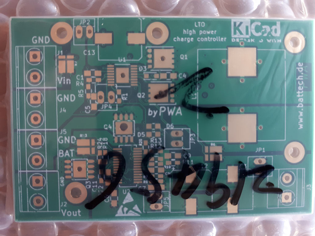
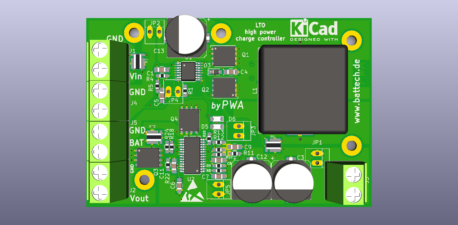
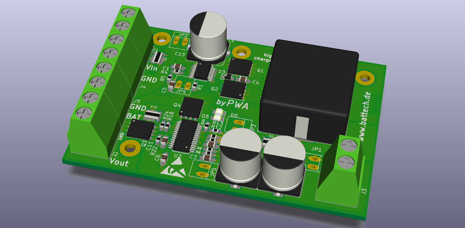
Assembled and tested prototypes
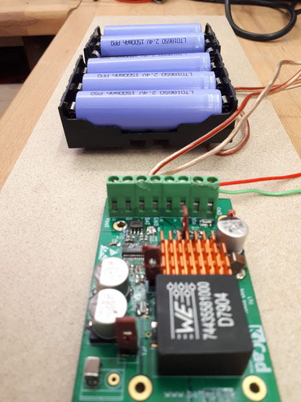
First integrations shows some features with the schematic, but in general it could be demonstated that the charger charges the LTO 18650 cells with 10Amps.
A fully charge cycle takes arround 10 mins (with LTO18650 round cells). This was very impressive. Some deeper investigations are needed.
During this fast charge/discharge test i observed some variations of the internal resistance.
For the next step i decided to create a new revision of the LTO charger with BMS function. Further details of the BMS function will be reported. If there are some detailed questions please conntact me: meyer@battech.de