CO2-Ampel / Corona / Lüften / Luftqualität-17.10.2020
Hier entsteht eine Anleitung zum Nachbau einer CO2-Ampel. Diese CO2-Ampel soll den CO2 Wert in einem Raum Messen und dieses beim Überschreiten eines eingstellten Maximalwert Signalisieren (z.B. eine oder mehrere LEDs angezeit werden)
Einsatzgebiet:
- CO2 Messung in Räumen
- Lüftungsverhalten anhand der CO2-Ampel anpassen z.B. in Schulen oder Büro's
Durch das bessere Lüftungsverhalten wird die Corona Viren Konzentration in einem Raum verringert.
Siehe BMAS (bez. Corona) Link: Empfehlung zum infektionsschutzgerechten Lüften
Folgende Komponenten werden als Prototyp verwendet:
- CO2 Sensor: CS811
-
- Bezugsqelle: Reichelt Elektronik Artikel-Nr.: DEBO SENS CCS811
- ARDUINO UNO DIP2:
-
- Bezugsqelle: Reichelt Elektronik Artikel-Nr.: ARDUINO UNO DIP2


Sobald die Komponenten geliefert worden sind und einen ersten Prototyp aufgebaut wurde, werde ich eine Nachbauanleitung online Stellen.
Ziel ist es eine kleine Smarte Lösung zu entwickeln (Möglichst Kostengünstig), welche drei LEDs hat, die den aktuellen CO2 Wert in form einer Ampel anzeigt.
grün --> alles OK
gelb --> CO2 Wert > 800 ppm
rot --> CO2 Wert > 1000 ppm
Ein entsprechendes PCB wird es dann zu erwerben geben. (Hoffentlich Kurzfristig)
Updates folgen.
Latest LTO-Blog entry
November 2018
LED Driver Board design (LTC3490)
The LED driver boad can be supplied from 1V to 4V so its perfectly suitable for one cell lithium ionen battery use. I designed 8 high power LED's (3535 size, Cree or equivalent) with an constant current of 350mA.
August 2018
LTO - BLOG update with block diagram and functional advantages of active BMS
Phase two is currently under development. The schematic is currently 80% finished.
I decided to implement additional possibilities to use different Microcontroller types such as:
- Arduino compatible slot for MKT pinout -> called (BMSDuino)
- Teensy 3.6 pinout
- Max1000 IoT (FPGA) - no SW - only HW implementation of active BMS
The advantages of a HW-controlled systems is that the security due to the fact that the HW can be fully verified. A software solution is much more complicated to make it highly save and relible.
May 2018
New - LTO - BLOG
Now added a LTO-BLOG. At this blog I discribe the development of a LTO-BMS / LiIon BMS (Lithium Titanate Oxide Battery Management System). The project is devided into several sub projects.
-
LiIon (Lithium Ion) charger as a stand alone module.
- This module consists a LiIon charger in combination with a trational Step-Down Converter. The charger circuit (LTc4000-1) controls the Step-Down converter (LT3845). This module can be directly connected to a 30V-60V solar panel and has an integrated Maxmimum Power Point tracker.
- Currently i finished the schematic and the PCB design. The PCB is under production and the components are ordered.
-
LiIon (Lithium Ion) balancing circuit.
- This design is currently not started but the BMS should be a active one and should support the LTO technology.
- LiIon Monitoring and Protection circuit
- Integration of all three circuits to one system
- Industrialization and cost optimization
Don't hassitate to give me some feedback or other impules for the LTO-BMS.
Tech-reviews / HowTo's /Tutorials
February 2018
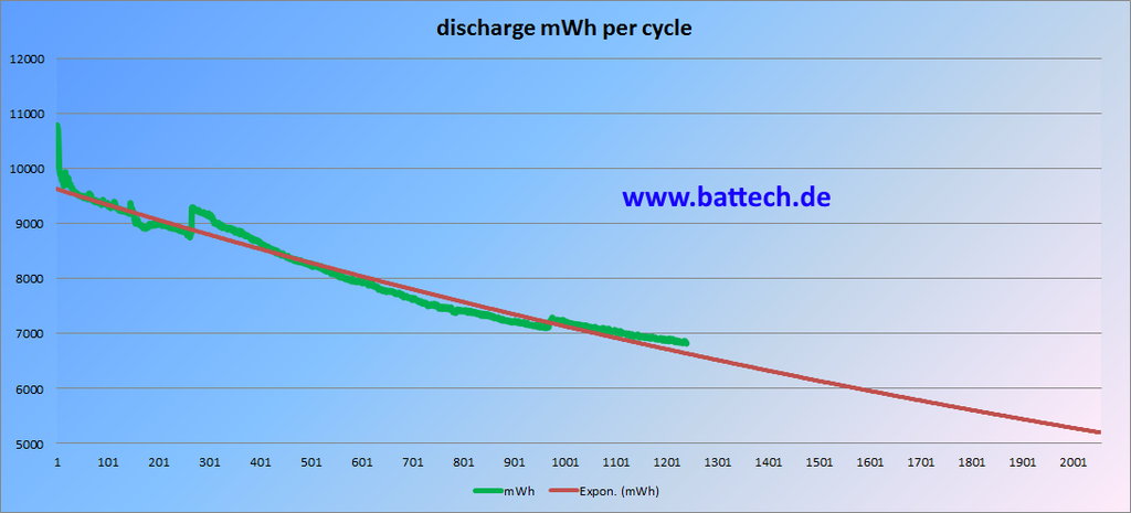
New measurement result of long duration accu test (extreme cycle test).
Discharge curve with over 1200 cycles added for the NCR18650B Panasonic battery.

January 2018
Konzept einer lithium Batterie für Wohnmobile:
